30 Results
View results:
Sort by:

In RFEM 6 it is possible to save selected objects (as well as whole structures) as blocks and reuse them in other models. Three types of blocks can be distinguished: non-parameterized, parameterized, and dynamic blocks (via JavaScript). This article will focus on the first block type (non-parameterized).

To simulate a support clearance in a connection between members, you can use the "Diagram" function for member hinges. To use this function, first define the relevant degree of freedom as release. Then, you can select the "Diagram" function from the drop‑down list.
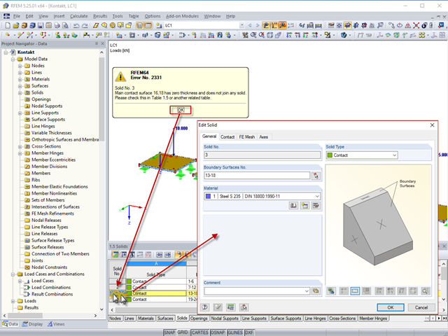
By double‑clicking the element numbers (first column) of the table, the corresponding dialog box appears.
.png?mw=640&hash=bfebd5ea2d4f77a817fa987424a23a799b3fe711)
When you perform the subsequent modeling of a beam under an existing floor, the first issues that arise are which forces should be transferred between the downstand beam and the floor, and whether a composite effect is the goal. In this case, the floor should rest on the downstand beam without a composite.

Steel-fiber-reinforced concrete is mainly used nowadays for industrial floors or hall floors, foundation plates with low loads, basement walls, and basement floors. Since the publication in 2010 of the first guideline about steel-fiber-reinforced concrete by the German Committee for Reinforced Concrete (DAfStb), a structural engineer can use standards for the design of the steel fiber-reinforced concrete composite material, which makes the use of fiber-reinforced concrete increasingly popular in construction. This article describes the nonlinear calculation of a foundation plate made of steel fiber-reinforced concrete in the ultimate limit state with the FEA software RFEM.

When evaluating line support forces, implausible diagrams sometimes arise at first glance. In particular, for variable loads at locations that also have a nodal support, at division points and edge locations of supported lines, the results sometimes show unexpected support reactions. Using the function of the linear smooth distribution in Project Navigator – Display does not always lead to the expected result diagram.

Determining the Material Properties of Steel-Fiber-Reinforced Concrete and Their Application in RFEM
Steel-fiber-reinforced concrete is mainly used nowadays for industrial floors or hall floors, foundation plates with low loads, basement walls, and basement floors. Since the publication in 2010 of the first guideline about steel-fiber-reinforced concrete by the German Committee for Reinforced Concrete (DAfStb), a structural engineer can use standards for the design of the steel fiber-reinforced concrete composite material, which makes the use of fiber-reinforced concrete increasingly popular in construction. This article explains the individual material parameters of steel-fiber-reinforced concrete and how to deal with these material parameters in the FEM program RFEM.
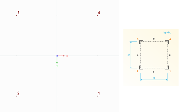
The following technical article describes the creation of a user-defined platform for use on a four-sided tower in the RF-/TOWER add-on modules. First, start with an empty model of the 3D type and define four nodes. The numbering and position of these nodes are very important here.

The stiffening of timber structures is usually carried out by means of timber panels. For this purpose, structural components consisting of slabs (chipboard, OSB) are connected with members. Several articles will describe the basics of this construction method and the calculation in the RFEM program. This first article describes the basic determination of the stiffnesses as well as the calculation.
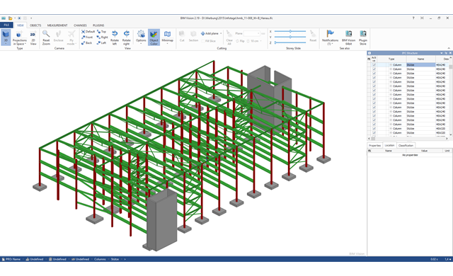
Building Information Modeling is making headlines in building design. While some engineers only use BIM methods for planning, others are dealing with this topic for the first time or rarely have time for it in their daily working routine. However, one topic seems the most important in structural engineering: How can structural engineers benefit from BIM?
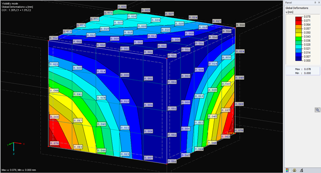
The deformations of the FE nodes are always the first result of an FE calculation. It is possible to calculate strains, internal forces, and stresses based on these deformations and the stiffness of the elements.
With RF-PUNCH Pro, the punching shear design can be performed according to 6.4, EN 1992-1-1. In the following example, the design according to DIN EN 1992-1-1 will be presented first with automatic design of the inner and outer perimeters and then on the basis of the inner perimeters defined by the user on a simple example.

RFEM offers the following options to design a pinned end plate connection. First, there is the option in RF-JOINTS Steel - Pinned to enter the corresponding parameters quickly and easily to receive a documented analysis, including graphics. It is also possible to model such a connection individually in RFEM and then to evaluate or manually design the results. In the following example, the particularities of this modeling will be explained and the shear forces of the bolts will be compared to the corresponding results from RF-JOINTS Steel - Pinned.
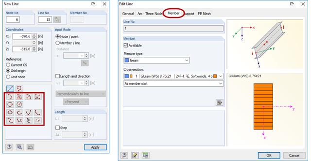
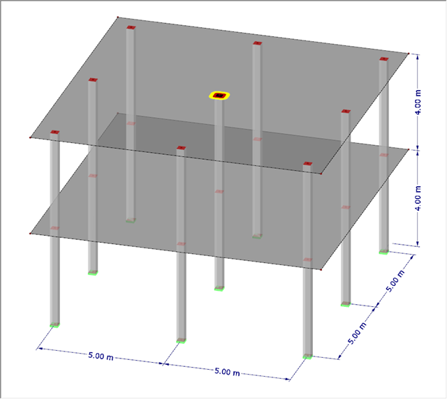
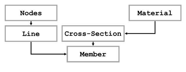
RFEM offers the possibility to model also curved beams. To do this, a curved line must be created first (see Figure 01). This line can then be assigned a beam with a cross-section. The advantages over modeling with beam segments are easier handling during the modeling, as well as a clearer result output of the internal forces.
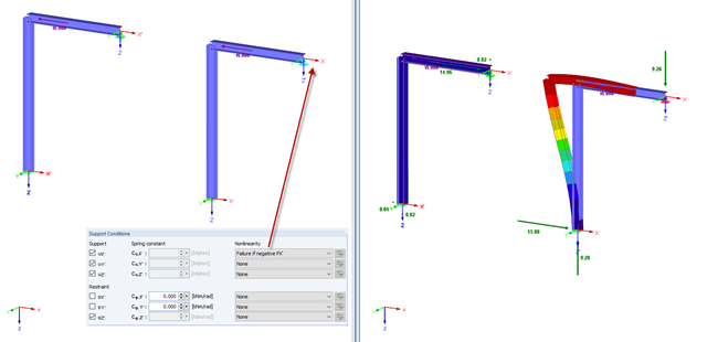
In practice, an engineer often faces the task of representing the support conditions as close to the reality as possible in order to be able to analyze the deformations and internal forces of the structure subjected to their influence and to enable construction that is as cost-effective as possible. RFEM and RSTAB provide numerous options for defining nonlinear nodal supports. The first section of my article describes the options for creating a nonlinear free support and provides a simple example. For a better understanding, the result is always compared to a linearly defined support.
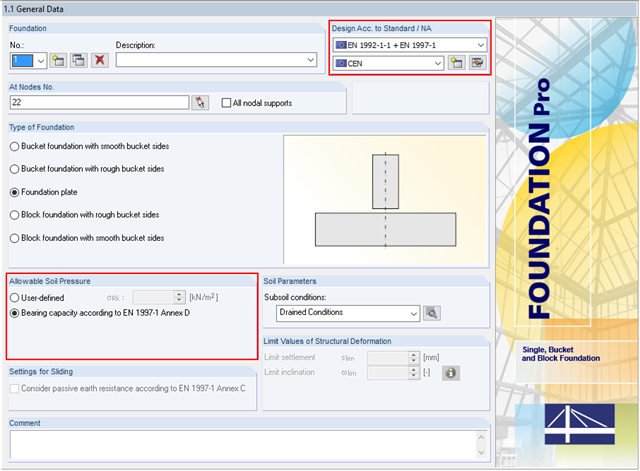
In addition to the reinforced concrete design according to EN 1992‑1‑1, RF-/FOUNDATION Pro allows you to perform geotechnical designs according to EN 1997‑1. In RF-/FOUNDATION Pro, the design of the allowable soil pressure is performed as a ground failure resistance design. If you select CEN as National Annex, you have two options for defining the ground failure resistance. First, you can directly specify the allowable characteristic value of the soil pressure σRk. Second, there is also the option to analytically determine the bearing capacity according to [1], Annex D.
![Residual Stresses, Zero Line Position, and Tearing Depth when Cooling Pane on both Sides [2]](/en/webimage/009621/2419687/01-en-png-png.png?mw=640&hash=5e657e3feb5c1bb6d21727468dd85d91e1c9f29f)
Generally, avoiding cracking in concrete structures is neither possible nor necessary. However, cracking must be limited in a way so that the proper use, appearance, and durability of the structure are not affected. Therefore, limiting the crack width does not mean preventing from the crack formation, but restricting the crack width to harmless values.
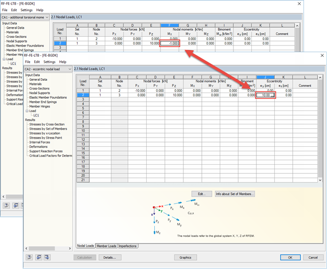
There are two ways to specify eccentric nodal loads in RF-/FE-LTB. First, the nodal load has to be applied in the right direction. Then, you can assign either the resulting torsional moment or the eccentricity.
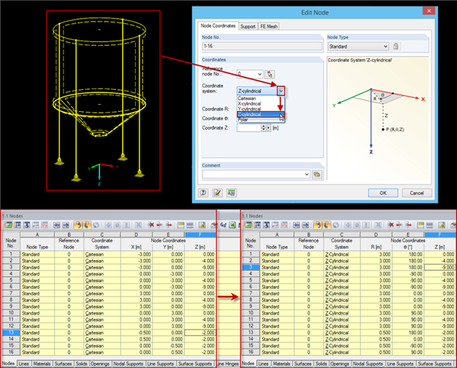
Rotation-symmetric structures or structural components are frequently entered in the Cartesian coordinate system. For example, subsequently changing the radius requires some effort, as the coordinates should be recalculated first and then updated for each node.
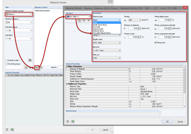
At first glance, the material list for masonry seems empty. The reason for this is that bricks and mortar can be used in many combinations, which would lead to a very long and unclear list. Therefore, it is necessary first to create a new material for masonry in order to consider these possible combinations in the calculation.
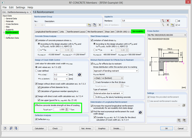
As of program version 5.06, you can use the option to adjust the effective concrete tensile strength fct,eff,wk at the time of cracking. At the start of the SLS design, the program checks whether the internal forces can cause cracks in the concrete. For this, the effective concrete tensile strength at the time of cracking is applied. You can adjust the strength via the factor. The calculation details display the adjusted value.

As in RFEM, load combinations can be generated automatically in RF‑PIPING. This feature is activated by default and creates the recommended load and result combinations for piping design. It is necessary to assign the relevant action category to load cases in order to generate the correct combinations. To do this, new action categories have been implemented specifically for loads on piping.
Pressure temperature conditions are generated as the sets of the first (second, third, and so on) load case of the "Pressure" category and the first (second, third, and so on) load case of the "Temperature" category. The default setting can be reviewed or adjusted in the "Grouping of Thermal and Internal Pressure Load Cases for Operating Combinations" dialog box. You can access this dialog box by clicking the corresponding button in the "Piping Load Combinations" tab of the "Load Cases and Combinations" dialog box. This dialog box is automatically offered to check your entries in the case of any change of the load case from the "Pressure" or "Temperature" category.
Pressure temperature conditions are generated as the sets of the first (second, third, and so on) load case of the "Pressure" category and the first (second, third, and so on) load case of the "Temperature" category. The default setting can be reviewed or adjusted in the "Grouping of Thermal and Internal Pressure Load Cases for Operating Combinations" dialog box. You can access this dialog box by clicking the corresponding button in the "Piping Load Combinations" tab of the "Load Cases and Combinations" dialog box. This dialog box is automatically offered to check your entries in the case of any change of the load case from the "Pressure" or "Temperature" category.
The first part of the article series about the COM interface described opening and creating a model in RFEM. The second part explains creating and modifying elements on an example of a member. The elements described in Part 1 will not be explained again here.
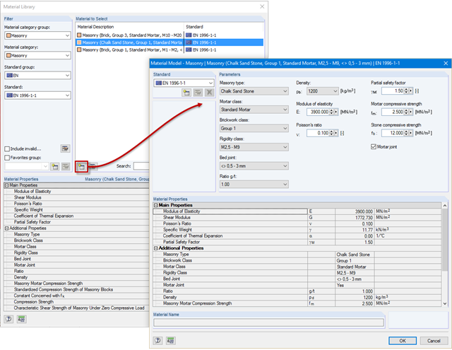
In order to estimate the structural behavior of masonry close to reality by using RFEM, it is necessary to select a material and a material model first. Since masonry responds to tension by cracking, you have to select a nonlinear material model. This can be selected if the RF-MAT NL add-on module is available.
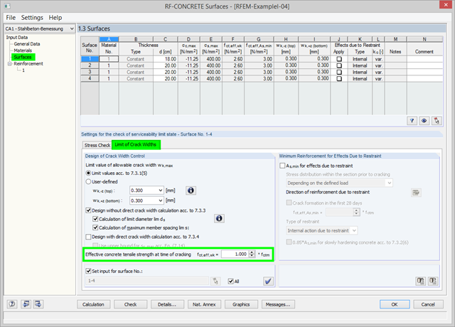
As of RFEM Version 5.06, there is the option in RF‑CONCRETE Surfaces to adjust the effective concrete tensile strength at the time of cracking. At the start of the SLS design, the program checks whether the internal forces can cause cracks in the concrete. For this, the effective concrete tensile strength at the time of cracking is applied. You can adjust the strength via the factor. The calculation details display the adjusted value.
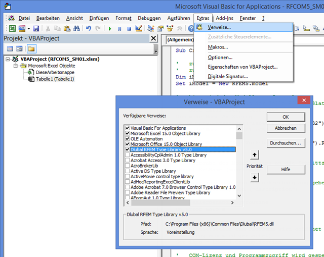
The first part of the post about the COM interface describes opening and closing RFEM. VBA programming language is used in Excel; however, the program sequence is the same as for programming with C#. First, it is necessary to add the corresponding reference in VBA to recognize the commands for the interface. The image on the left shows an example of RFEM 5.

In the following example, the stability analysis of a steel frame can be performed according to the General Method in compliance with EN 1993‑1‑1, Sect. 6.3.4 in the RF‑/STEEL EC3 add-on module. The first of my three posts shows the determination of the critical load factor for design loads required by the design concept, which reaches the elastic critical buckling load with deformations from the main framework plane.
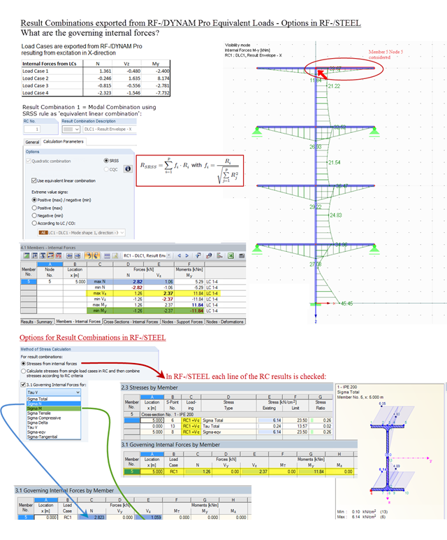
Result combinations exported from RF‑/DYNAM Pro – Equivalent Loads are generated by superimposing the results from the individual modal responses. For this, the SRSS rule can be used as "equivalent linear combination". When result combinations are used in RF‑/STEEL, two options are available for calculating stresses. In the first option, the results from the result combinations are used directly. This is done line by line, for each maximum and minimum controlling internal force. In the second option, stresses are determined from the individual load cases. The quadratic superposition rule is then performed again in RF-/STEEL.
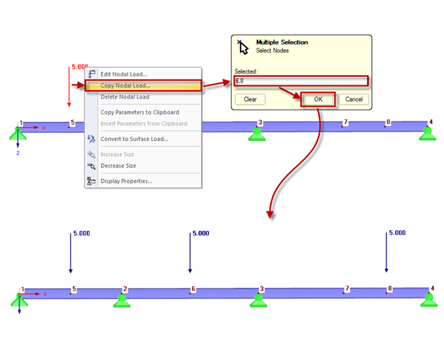
You can quickly copy nodal loads to other nodes using the "Copy Nodal Load" option in the shortcut menu. To do this, select the nodal loads to be copied first, then click the "Copy Nodal Load" option in the shortcut menu. A "Multiple Selection" window appears where you can enter the relevant nodes to which the nodal load is to be copied. After clicking "OK" to close the window, the nodal load is copied.
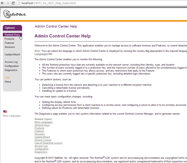
A network dongle is the appropriate solution to ensure security for licensing within companies working with several RFEM and/or RSTAB licenses. First, the dongle is placed on a central server. The licenses are then requested by RFEM and RSTAB, as well as all other stand-alone programs, from this dongle via the network.